Construction plans, blueprints, drawings—however you refer to them, they are essential for construction projects of any size.
They tell everyone from the project owner to on-site workers what is actually going to be built.
Thus, all those involved in construction projects should be able to read the construction plan.
However, that requires some skill and can be overwhelming for first-time readers.
With so many elements to consider, it’s hard to know where to start. Here’s how you can read construction plans like a pro in five steps.
In this article...
Read the Title Block
A construction plan is a collection of two-dimensional drawings (blueprints) that show what will be built and what it will look like after a construction project is completed. It contains information in the form of dimensions, symbols, abbreviations, and line types.
Regardless of the type of construction drawings you’re reading, you’ll usually find the title block on every sheet you look at.
The title block is indispensable, since it provides critical information about the project in general and that drawing sheet in particular.
Here are a few examples.
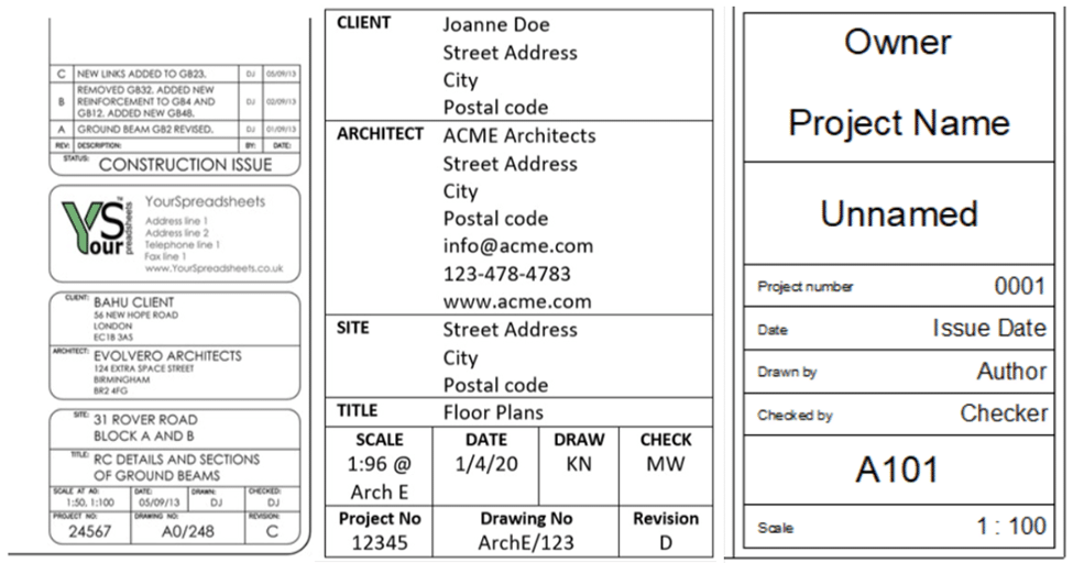
As you can see, the style and order of information in a title card can vary.
Still, there are some essential elements that appear in all of them, such as:
- the name of the project
- the client’s name
- the name of the architect, designer, or engineer
- drawing title
- issue date
- scale
- sheet number
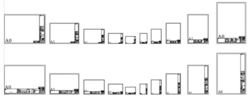
The title block can be placed in the bottom right corner or along the right vertical or lower horizontal edge of the sheet.
However, you’ll never find it on the left side of the sheet because that’s where blueprints are bound after printing.
Here’s what title blocks look like on different paper sizes.
In addition to all that information, the bottom right corner will also contain the drawing or print number, which is important for finding other referenced drawings or submitting them to different approval authorities.
Lastly, the title block usually includes a revision block, which starts empty and then gets filled out as the drawing changes.
They too can appear in many different forms depending on what the designer and other involved professionals consider necessary.
All in all, reading the title block first will give you baseline information about the project and specific details about that particular drawing and its place within a set of construction plans, thus putting you on the right track.
Go Over the Plan Legend
Going over the plan legend is the next logical step in reading construction plans.
Construction projects are complex by their nature, and the purpose of the plan legend is to guide you through them.
A set of construction plans will consist of many different types of drawings:
- floor plans
- section and elevation drawings
- structural drawings
- electrical drawings
- HVAC drawings
- plumbing drawings
- finishing drawings
Regardless of their type, each plan, drawing, or blueprint needs to show a lot of information in a limited space to be effective.
To do that, they rely on various sets of standardized or customized symbols and abbreviations.
However, these would be hard to understand without plan legends acting as a guide. Here’s an example.
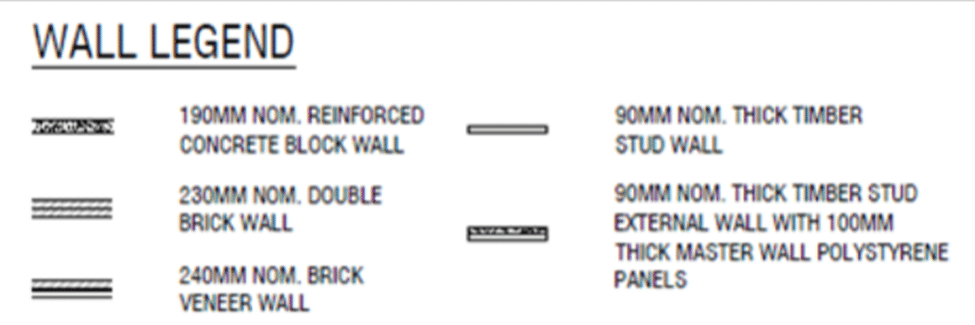
This simple wall legend tells you that the blueprint in front of you shows five types of walls depicted by different line weights and styles.
It also tells you what building material will be used for each and their thickness in millimeters.
So, this legend effectively relayed plenty of information that different project stakeholders can use.
For example, this allows contractors to estimate the quantity and cost of building materials and the associated labor costs, enabling them to give a quote.
Or, when construction is underway, this information guides the workers’ actions, telling them what they’re building.
Of course, legends can be much more complex, depending on what they’re showing. Here’s an electrical plan legend.
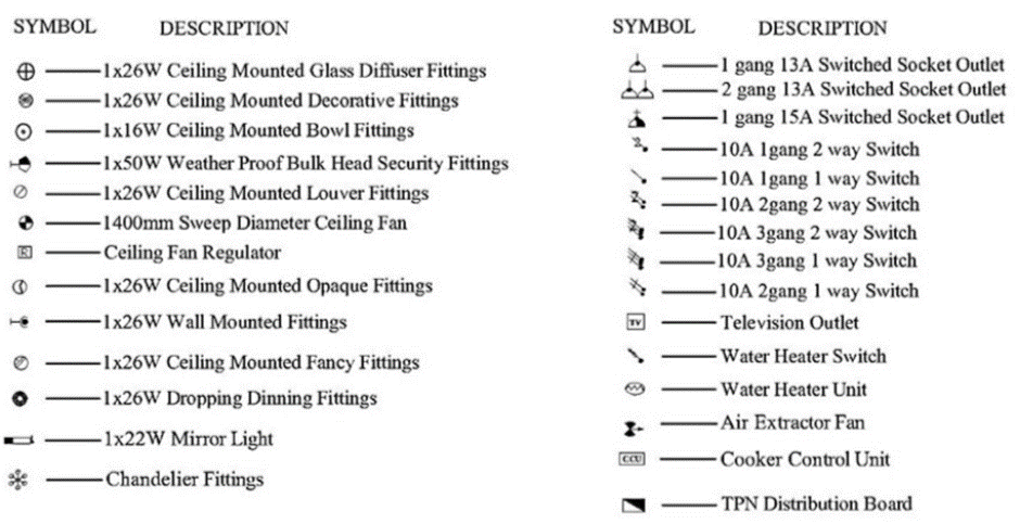
Although there are many more symbols, in an electrical plan, all of them refer to different electrical fittings, sockets, and switches. In the case of fittings, the legend gives their wattage, mounting location, and type.
The symbols in a plan legend are mostly standardized and often look like the stylized versions of their real-life counterparts, such as staircases, toilets, bathtubs, stoves, etc.
Others are also commonly known to represent elements like walls, doors, and windows.
However, there are possible differences even in their interpretation. That’s why studying the plan legend is an essential step in reading construction plans.
Inspect the Drawings
After reading the title block and the legend(s), it’s time to inspect the drawings.
Similar to when projects are created, it’s best to start with architectural drawings, as they help you visualize the project’s outcome.
However, there are some things you should know before you inspect those and other drawings.
The first thing is gridlines. Although they may not appear on all blueprints, they’re usually an essential element of construction drawings.
Simply put, they’re used to pinpoint a specific area on the drawing. For example, this is a foundation plan where gridlines are highlighted in red:
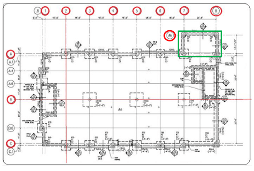
So, if builders run into an issue while laying foundations, they would contact the structural engineer about a problem in, for instance, grid section AA-8, which is marked above in green.
In this case, the grid reference avoids confusion in communications.
The grid also ensures that drawings are coordinated, especially when done by different teams.
In the planning stage, this can prevent clashes between different construction elements like, for instance, lights overlapping with sprinklers.
The second thing you should consider is the scale to which a blueprint is drawn.
In a nutshell, everything in a drawing is reduced (or sometimes enlarged) in the same proportion to one another.
For example, the commonly used scale for floor plans is, according to Google, the one-quarter scale (1/4”), where one-quarter inch on the floor plan equals one foot in real life.
The drawing scale will be clearly noted and often supported by a scale bar to help visualize it.
Here’s an example of standard architectural scale bars shown in the imperial and metric systems.
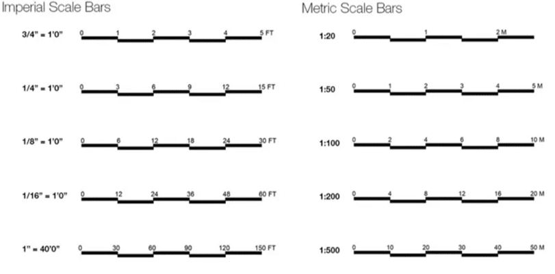
You can see that the one-quarter scale corresponds to the 1:50 metric scale where, for instance, 1 centimeter on the drawing represents 50 centimeters in the real world.
The fact is that the actual conversion from imperial to metric is 1:48, and the closest standard metric scale is 1:50.
You can see other actual and closest standard scale conversions on this cheat sheet:
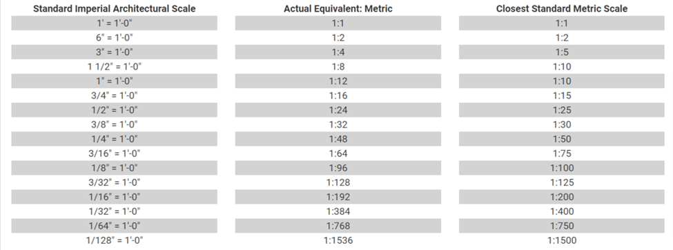
Thus, knowing how to use the gridlines and understanding the scale will significantly enhance your ability to read construction plans.
Determine Orientation
Determining the orientation of buildings and other structures on a construction site or the orientation of rooms and elements on a floor plan is crucial for performing actual construction tasks.
What’s more, in recent times, building orientation has regained popularity as a tool for raising the energy efficiency of houses and buildings.
No matter the size, every site plan should have an arrow or a compass pointing north.
Therefore, symbols like the ones below are usually found next to the plan legend.
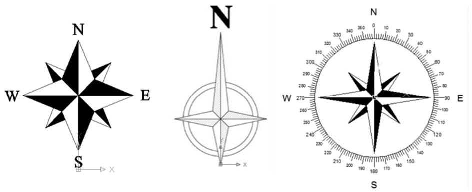
This is called the true north and corresponds to the direction of the geographic North Pole.
However, many other drawings will not show the true north, only the project north. Occasionally, both will be present, as this user of the Archinect Forum shares:

So, why two norths? And what’s the difference?
The project or plan north is how architects and designers present their plans on a sheet. For example, the longer side of a house will occupy the longer side of the paper, meaning that the project north is usually the top of the blueprint.
We say usually because sometimes the project north may face downwards or any other direction.
For example, the left image below shows a model laid out with the project north going straight up, while the orange arrow shows the true north.
The image on the right shows how the model is positioned in the real world in relation to the true north, which is now a straight-up arrow.
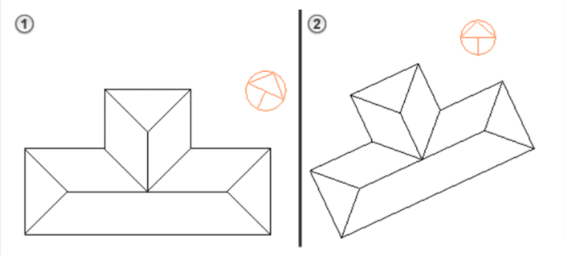
The other thing to know about the orientation is its role in making houses and buildings more energy efficient.
Both the orientation of a building on the land plot and the interior arrangement of rooms can be optimized to use solar and wind power to save on heating, cooling, and lighting costs.
For example, more frequently used rooms can be placed on the south side to get more sun in the winter.
The same is true for decks and patios that will be used more if they’re on the south side.
If you want to orientate yourself better when plans are concerned, you can read about the six elements of construction project planning.
In conclusion, understanding the orientation of on-site structures and interior elements plays a vital role in performing different construction tasks and helps in understanding modern construction.
Look for Any Notes Added
Usually found below or near the plan legend, notes are the crucial element of construction blueprints that either explain different items on the drawing or tie each drawing sheet to the relevant specifications.
Thus, studying the notes is essential for understanding the drawing and finding the right specifications.
First, let’s dispense with different types of notes that can appear on various blueprints. Despite many variations, you’ll usually see all or some of them on the drawing you’re looking at.
General notes usually come first. These apply to the entire construction project, i.e., all drawing sheets and all construction disciplines.
They are sometimes followed by general discipline notes. These notes are intended for specific design disciplines, e.g., architectural, engineering, or masonry notes, and should list the discipline they refer to.
Then come general sheet notes. They are relevant only for that sheet in a set of construction drawings. On a floor plan, they can look like this:

So, when you find, for example, the letter E on the drawing, you’ll know where the fire-rated access door is supposed to go.
In general, keynotes are a kind of drawing legend that simplify notations in complex blueprints.
They usually have numbers in circles and sometimes arrows that point to the described item. However, arrows may be omitted due to spatial limitations.
Their numbers start over on each sheet; thus, the keynote 12 on one sheet is not the same as the keynote 12 on the other.
Here’s an example of four ways in which they can be shown:

The first one shows the circled numbers on a drawing, and keynotes say what they mean. The second adds a discipline, thus making clear for whom these notes are intended.
The third one replaces circled numbers with the specification reference number followed by a unique suffix that identifies the item.
The fourth one omits keynotes altogether and uses only a drawing to show both the identifying number and description.
Before computer-aided design (CAD) software became a standard way to create blueprints (like what building information modeling (BIM) software is becoming now), notes had to be kept to a minimum.
But, with the advent of CAD, it became much easier to incorporate them into plans.
This often leads to designers stuffing too much information onto a single sheet.
That’s why notes frequently refer to items that are already covered elsewhere in the specifications, which can, in case of discrepancies, lead to requests for information (RFI) or even change orders.
In such cases, the usual rule of thumb is that specifications take precedence over the drawing.
To sum up, using the notes will greatly improve your plan-reading skills and can even prevent costly mistakes.
Conclusion
So, we’ve gone through the five essential steps required for reading construction plans.
After you’ve read the title block, studied the plan legend, inspected the drawings, determined the orientation, and examined the notes, you should have a much better understanding of construction blueprints, which is necessary to do your job like a pro.


